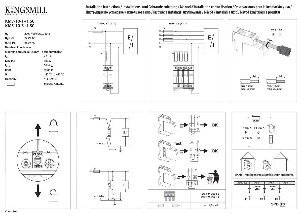
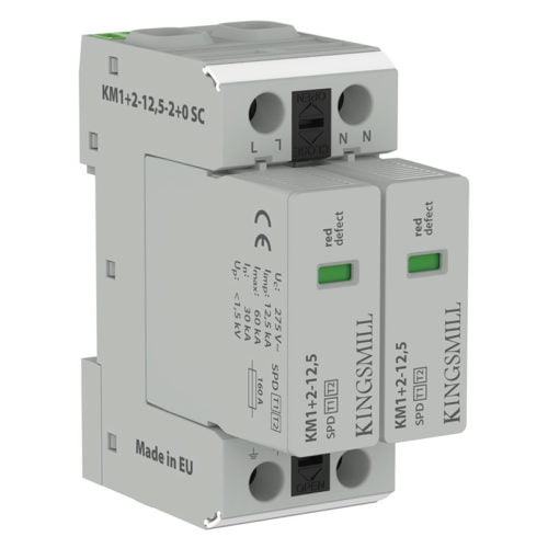
Product Information:
Combination of varistor SPD and encapsulated spark gap connected in the 1 + 1 mode. Use in TT systems on the boundary of LPZ1 and LPZ2.
Suitable for houses, commercial and industrial buildings.
Kingsmill fully coordinated mains devices to provide complete protection from entry point to equipment.
Features:
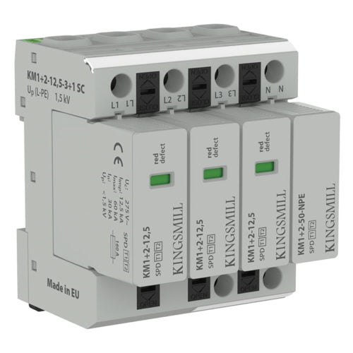
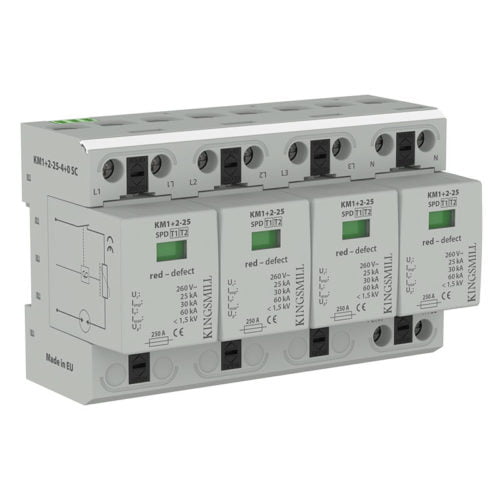
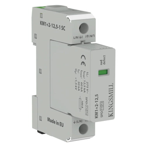
- Remote signalling
- Reversible installation
- Biconnect terminals
- Locking pluggable modules
- Optical lifetime status indication
Benefits: No follow-through current. No leakage current. Coordinated range (install in close proximity to each other)
Standards: BS:EN 62305 (Lightning Protection) and EN 61643-11 (Surge Protection Devices).
LPL I + II
System: Single Phase TT
MDB: Boundary of LPZ0 and LPZ1
SDB: Boundary of LPZ1 and LPZ2 if >100m away from MDB.
LPL III + IV
System: Single Phase TT
MDB: –
SDB: Boundary of LPZ1 & LPZ2 if >100m away from MDB.
More Information:
A lightning surge protection device prevents damage to electrical and electronic equipment from transient over-voltage events by blocking or redirecting surge current to the ground instead of passing through the equipment.In a well -designed system, it is important that for each building, both the incoming and outgoing circuits are protected by surge protection devices (where the cables enter and exit the building).
This includes:
- Mains power supplies – including UPS
- Telephone lines
- Data communication lines
- Instrumentation, control, signaling lines
- Coaxial lines for CCTV, TV, & antenna cables
Field based electronic equipment also need to be protected.